
The Column Stability Factor ... EXAMPLES
Lesson 15

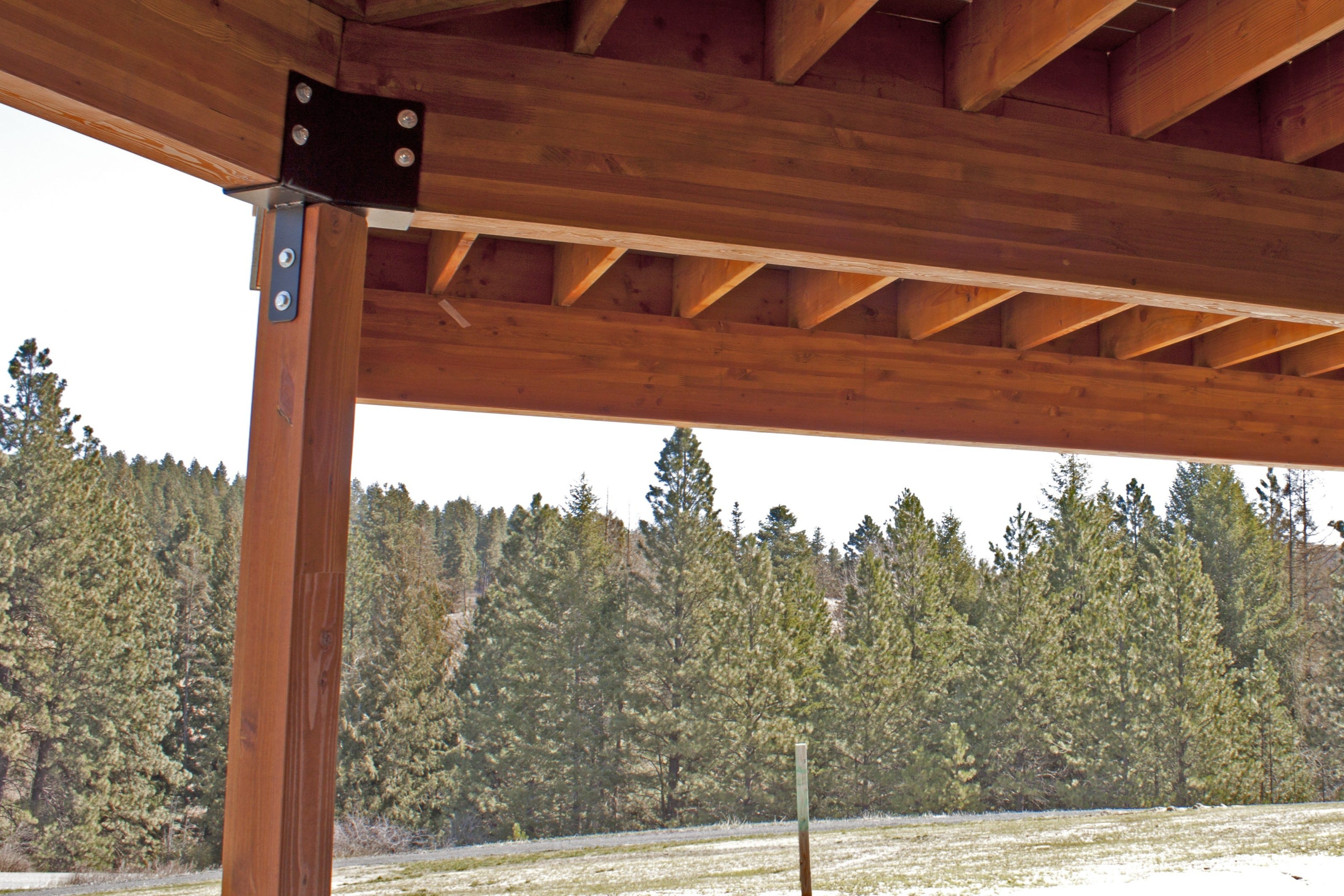
In the last lesson we talked generally about column stability. A wood column (or `post’) is really pretty strong, as long as it is `stable’. To keep it stable, we need to either brace it, so that it can’t bend, flex, buckle, at all, or consider the reduction in capacity to make sure it’s still stable, even if not completely braced. We reduce its capacity, to keep it stable, if necessary, through the Column Stability factor, CP. The Column Stability factor is an adjustment to the Compression Parallel to Grain design check, for a column, post (or any compression member). It’s a tiny bit misleading, as the stability of a column is dependent on the column’s stiffness … and yet we deal with it through a strength adjustment. Let’s take a look.
From Section 3.7 of the National Design Specification (NDS),
CP = [ 1 + (FcE / Fc*) ] / 2c + √ ({ [ 1 + ( FcE / Fc*) ] / 2c } 2 - (FcE / Fc*) / c ) , where …
Wait! … that’s hard to read, let me hand-write it …
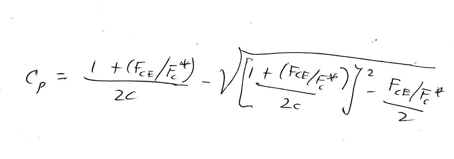
Okay, … `where’ …
FcE = 0.822 Eminʹ / (ℓe / d)2 ,
where
Eminʹ is the adjusted modulus of elasticity with respect to the direction of potential buckling,
ℓe is the effective buckling length, and
d is the column depth or thickness (dimension) in the plane of potential buckling.
For most wood framing situations, the effective length is essentially the unbraced length, where the column (post, stud, etc.) is assumed to be `pinned’ at top and bottom. In real life, a single bolt at the top and bottom may imitate a `pin’, but, in most cases, multiple bolts, nails, etc. are also taken to provide the pinned-pinned connection. And most real-life resistance to pin-type rotation only makes the pinned-pinned assumption conservative (if only a bit). The only situations where the pinned-pinned connection is not suitable would be: 1) the rigid base (as though embedded in concrete) and top `free’, or 2) the bottom pinned, and the top rigid (`sidesway’). In these two cases the effective length is greater than the `actual’ column length, and the column is more unstable, than if pinned-pinned. (Take a look at Appendix G in the NDS, as a start for further study.)
Oh,
Fc* = Fc multiplied by all applicable adjustment factors except CP,
and … c is …
0.8 for sawn lumber,
0.85 for round timber poles and piles, and
0.90 for structural glued laminated timber, structural composite lumber, and cross-laminated timber … (basically deals with variability in E).
The column’s stiffness comes in via FcE. For tall, slender columns, stiffness is the deal! The column needs to be stiff enough, so that, if there’s a small amount of `bend’, flex, etc., the column has enough stiffness, to straighten back out. If not, the bend, however small, bends more through the induced bending moment (via eccentricity), and bends more, and bends more, until something bad happens (collapse, wood crushing, whatever). (At least that’s they way I explain it.) The stiffness, E, comes into play, seemingly indirectly, via CP.
Let’s do some examples.
From the previous Lesson …
4 x 4 by 16 feet tall … Southern Pine No. 2
Dimensions … 3.5 inch by 3.5 inch …
Fc = 1100 psi; Emin = 510,000 psi … (from the NDS Supplement).
Let’s assume the 4 x 4 supports a deck, outside, where there’s moisture … (`wet use’).
The Wet Service factor is (from the NDS Supplement), for our 4 x 4 Southern Pine … 0.80 on Fc, and 0.90 on E and Emin.
For the sake of the calculations, let’s assume otherwise normal conditions (CD = 1.00, etc.).
Here goes …
Eminʹ = 510,00 psi x 0.90 = 459,000 psi.
ℓe / d = 16 (12) in. / 3.5 in. = 54.9 … Oops … not ≤ 50 … `illegal’… can’t do. Move on!
What would be `legal’?
Try 50 / 54.9 x 16 ft = 14.58 ft.
ℓe / d = 14.58 (12) in. / 3.5 in. = 50. `Barely legal’.
Let’s run CP, just for `kicks and giggles’.
FcE = 0.822 Eminʹ / (ℓe / d)2 = 0.822 (459,000 psi) / (50.0)2 = 151 psi.
Fc* = 1100 psi (0.80) = 880 psi.
FcE / Fc* = 151 / 880 = 0.171.
c = 0.80, as for sawn lumber.
So,
CP = … 0.165.
So, 16-foot tall … illegal.
… 14.6 feet tall … legal, but look! … we lose over 83% of its otherwise braced allowable strength, since it’s so long and slender.
What’s its capacity in pounds?
P (allowable) = Fcʹ A, where
Fcʹ = Fc CD CM CP etc … = 1100 psi (1.0)(0.8)(0.165) = 145 psi.
A = 3.5 in. x 3.5 in. = 12.25 in.2.
P (allowable) = 145 psi (12.25 in.2.) = 1779 lb … call it 1780 lb.
What would the same 4 x 4, under the same conditions, except only 1 foot long, be capable of? … (deck close to ground).
Turns out … CP = 0.994.
We lose only the `tiniest’ bit of capacity due to potential buckling. Essentially negligible. Probably more `theoretical’ than real.
The same post has an allowable capacity of … 10,700 lb … (at only 12 inches tall).
As long as it’s centrically loaded …
A simple spreadsheet for Column Capacity and the Column Stability factor … is for your grab on the other side of the Paywall.
NOTE: if you were to ever see a 4 x 4, supporting, bare naked, a deck, 16 feet in the air … not only would it be `illegal’... it just wouldn’t look right (too slender … too unstable) … plus, I doubt you’d ever go up onto the deck.
Let’s do another example.
Consider a 5-1/8 x 7.5 DF Combination 2, 15 feet in height, supporting a roof beam, delivering a total snow-plus-dead load of 32,500 lb. The column is installed in the wall such that the weak dimension (5.125 inches) is braced by 2x6 wall framing and wall sheathing/covering, with the 7.5-inch dimension not flush with the wall (sticking out a bit … a nice look, actually). Thus, in the 7.5-inch direction, the column is not braced. Let’s examine if the column suitable for the given load (and installation) condition. Assume centric loading of the column.
Note: we could place the column in the other orientation, so that it’s basically flush with (in) the wall (2 x 6 framing). But, then the weak axis would not be braced. (Investigating the other orientation would make for a good homework problem.)
Load Condition
Total load, P = 32,500 lb.
Compression parallel to grain stress, fc …
fc = P / A.
A = 5.125 in. x 7.5 in. = 38.4 in.2.
fc = 32,500 lb / 38.4 in.2 = 846 psi.
Design Information
From the NDS Supplement …
FC = 1950 psi (4 or more lams), E (axial) min = 850,000 psi.
ℓe = ℓu = 15 feet (assume pinned-pinned),
d = 7.5 inches,
ℓe / d = 15 (12) / 7.5 = 24 … doesn’t exceed 50 … good!
… and so on, noting that Fc* = 1950 psi (1.15) = 2243 psi … (Snow Load Duration factor).
Crunching the rest of the numbers ...
CP = 0.493.
The column surrenders about 50 percent of it’s potential compressive strength to resist buckling.
Fcʹ = 1950 psi (1.15)(0.493) = 1106 psi.
Design Check
(Is) fc = P / A = 846 psi ≤ Fcʹ = Fc CD CP = 1950 psi (1.15)(0.493) = 1106 psi (?) … (Yes, good!)
A smaller section column might be possible … if we want to go smaller. (Maybe that would be a good homework problem … see if 5-1/8 x 6 would work?)
NOTE: 15 feet is a tall column. What if it was only 9 feet? (Another good homework problem.)
At 9 feet tall, CP … fleshes out to be … 0.877 … only a 12% reduction of capacity, to address stability.
+++++
Spreadsheet on other side of Paywall …